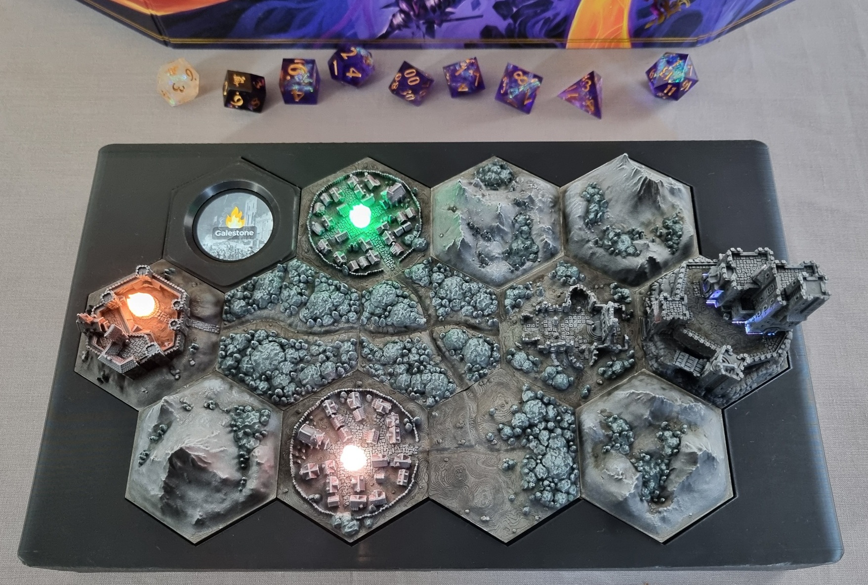
Over last Christmas break I wanted a project that would combine multiple of my creative interests: CAD, 3D printing, miniature painting, software engineering, electronics, and TTRPGs. Having just started to GM a Daggerheart Age of Umbra mini-campaign, and figuring that my electronics skills (being the most fledgling of the aforementioned interests) would just about allow me to blink some LED “sacred pyres”, the idea for this interactive hex map contraption was born.
Of course it took me far longer than my Christmas week off to complete! However, I was able to debut it during the 5th session of the campaign, just as my players managed to wrap up the first major story arc by reigniting an extinguished pyre. It was all worth it to see that single LED flicker back to life! 😂
Concept and design
The Age of Umbra is a dark-fantasy setting created by Matthew Mercer for Critical Role and their Daggerheart TTRPG. Inspired by games like Dark Souls, it features a bleak, godless world, sparsely populated by hardy survivors. Settlements of relative safety tend to cling around “sacred pyres”: large magical bonfires that keep the eponymous Umbra at bay.
My table’s rendition of this world is set in a valley around whose edges lie 3 towns: Galestone, Ransfall, and Blacktower, each with their own sacred pyre. The story would involve these pyres coming under threat of extinguishment or corruption, and the players would ultimately endeavour to reignite or cleanse them.
I wanted a prop that would visually show the world, the towns and their pyres, and allow me to extinguish/light/corrupt them from my laptop or from the console itself. It needed to look awesome – a piece of art in its own right – and be self-contained and portable.
I settled on the overall shape fairly quickly:
- Hexton Hills tiles would form the world map.
- RGB LEDs for the pyres so each state can be represented by a different colour (e.g. corrupted = green). Additionally I wanted them to flicker like a real fire/candle.
- Enclosed in a plastic 3D-printed housing.
- An ESP32 with circular display, embedded into the housing, for local and wireless control.
- Internal LiPo battery for portability.
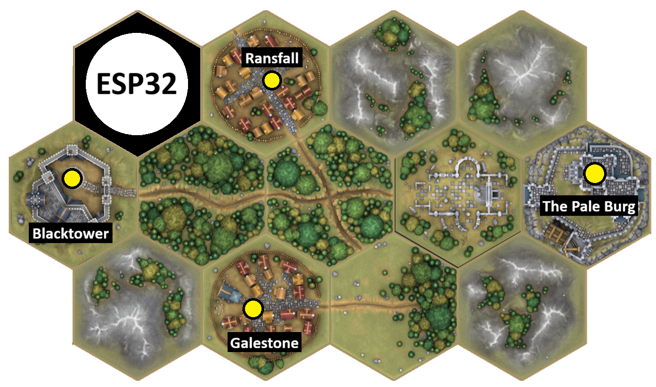
The closest I came to any design sketches was to use the Hexton Hills map builder to plan the configuration of map tiles, and where the ESP32 circular display would fit. A 4-5-4 map struck a good balance between showing all of the geographical features of the valley and keeping the console to a manageable size:
Microcontroller and display
A Waveshare ESP32-S3-Touch-LCD-1.28 was the perfect find for this project. It is an integrated development board that features:
- ESP32-S3 microcontroller with WiFi and GPIO.
- 1.28 inch circular touchscreen display (240x240 resolution).
- MX1.25 connector for a 3.7V LiPo battery.
- USB-C power and battery charging.
Crucially, its small and circular form-factor means it can fit inside a Hexton Hills-size hex, so I could embed it in the map on top of the console. Touchscreen and WiFi would allow me to interact with it locally and remotely. The ESP32-S3 supports a multitude of firmware environments including MicroPython and Arduino, so it would be straightforward to code for. Finally, the integrated charging circuit would take a lot of the complexity out of managing a LiPo battery.
Electronics
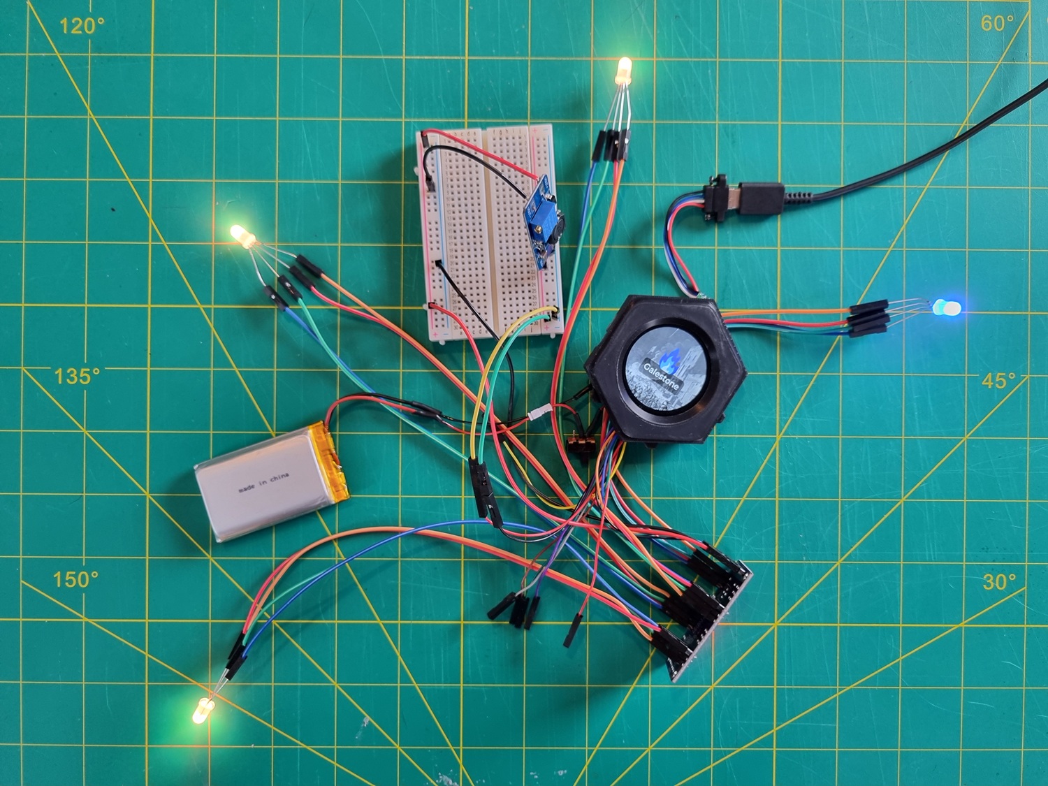
The board does not have enough GPIO ports broken out to drive 4x RGB LEDs without external help1, so I acquired a TLC5947 LED driver module2.
This is the first place where my inexperience with electronics really started to show! After hooking up a single RGB LED to the TLC5947, I attempted to power it from the 3V3 GPIO output, with no luck. Frustratingly, it did just about power the module’s onboard LED (dimly, but at this point I didn’t have a reference) so I thought the problem was elsewhere. After bashing my head against the wall for a while, I tried powering it from an external 9V PP3 battery and suddenly the LED lit up!
It took me another couple of experiments to figure out that the 3V3 output simply wasn’t capable of supplying enough current, and that I should instead be using the VSYS output, which sits on the system rail. This was an improvement: it worked great when connected to USB, pulling power at 5V. But when powered only by the LiPo battery, which ranged from 3.0-4.2V, the setup was very unstable. So, current was not the only story: the LiPo couldn’t provide enough voltage.
In hindsight I should have paid attention to the silkscreen text on the back of the module that says “V+ 5-24V” and I’d have immediately known what this problem was. To bring VSYS up to the 5V minimum, I connected an MT3608 boost converter in between, set to 5V. With this, everything worked perfectly, and I was able to drive all 4 RGB LEDs from battery and/or USB power through the dev board.
The full schematic can be found in the electronics directory of this project’s GitHub repo.
Power and wiring
With the main components sourced and confirmed working on my bench, the next task was to do some soldering and wire everything up. For convenience I opted to use Dupont connectors for most of the wiring. It looks very prototype but was quicker and less stressful, and seems to work fine!
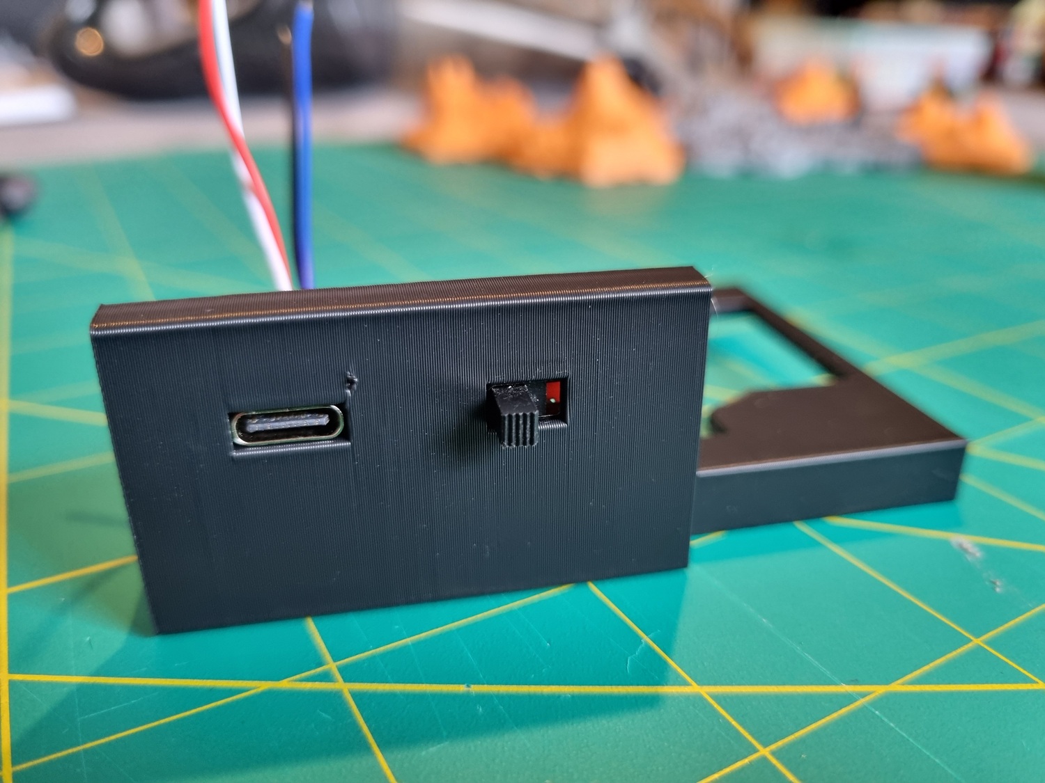
For the battery, I used a 3.7V 2000mAh 103454 LiPo which ends up providing about 6-7 hours of runtime. A slide switch connected between board and battery provides safe on/off power control. To facilitate charging, I constructed a male-to-female USB-C extension cable that could fit flush with the 3D-printed enclosure.
I wasn’t sure whether my LiPo cell actually had a Battery Management System (BMS): the PCB at its terminals seemed too small, more like a breakout. To ensure it was protected, I connected my own BMS. However, my testing showed it only tripped at ~2.5V… better than nothing but well below the recommended discharge cutoff of 3.0V past which a cell risks premature ageing and permanent damage.
Backlight issues under load
I later discovered that as the battery drops below about 50-60%, the screen backlight starts to visibly flicker. This gets really bad past about 40%, and is worse when software is doing something power-hungry like updating the UI or making a network request over WiFi. I tried putting some capacitors between the board and the battery but they didn’t help at all. It seems the backlight just has micro brownouts when current load spikes above baseline. I chalked this one up as “nothing I can do here”.
Software
I wanted to use Python for this project, as I’m very familiar with it and it seemed more appropriate for rapid-prototyping than Arduino. It ended up requiring custom MicroPython firmware builds so I don’t know if it saved me much time in aggregate!
The software stack comprises the following:
- Base firmware: custom build of lv_micropython (a MicroPython fork that includes the LVGL UI library). I patched the SoftSPI driver to make the MISO pin optional so I could use it to drive the TLC5947 LED module which is an output-only device.
- GC9A01 display driver: gc9a01_mpy built as a MicroPython user module.
- User interface framework: LVGL v9.3.
- HTTP server and API: Microdot.
All of the code, including MicroPython patches and build instructions, can be found in the firmware directory of this project’s GitHub repo.
Touchscreen UI
Having virtually no prior experience with microcontroller software development, I had no idea what to expect for developing UIs. Would it be like QBasic where I can only push a very limited set of primitives to screen, and I have to build everything from scratch? Or would it have a full-featured window-and-widget-based UI framework?
When I powered on the ESP32-S3 device, it was preloaded with a sophisticated touchscreen UI demo application but no documentation explained what it was. It took me far too long, including dumping the preloaded firmware, to figure out that it was just LVGL’s lv_demo_widgets()!
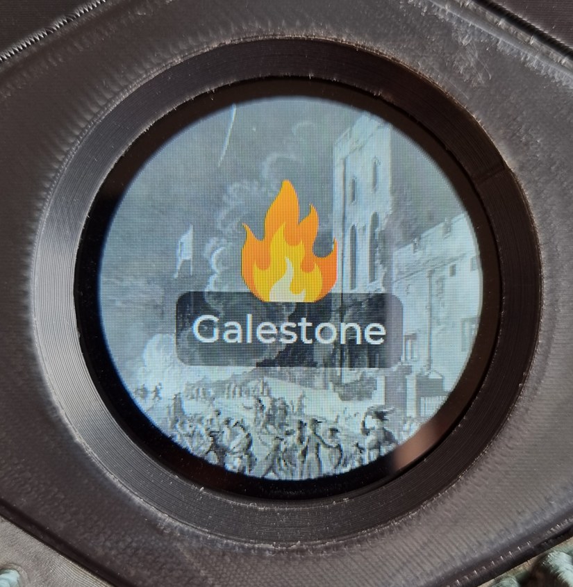
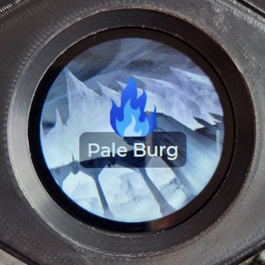
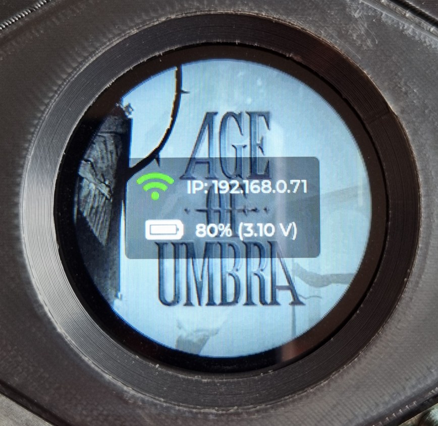
Because there would be multiple ways to control the state of the pyres – via the touchscreen and the HTTP API – I structured the app around a GameState source-of-truth model and the Observer Pattern to dispatch events. Each town has its own “screen” with an evocative background image3 and flame icon showing the colour/state of that town’s pyre. Pressing the icon cycles through the pyre states, and swiping left and right cycles the active town screen. Lastly, a status screen, showing battery level (percentage and ADC-reported V), WiFi connectivity, and IP address, is accessible by swiping down.
Implementation challenges included:
- Image decoding: the JPEG decoder is extremely slow and re-decodes the entire file on every repaint, even if only part of the image is invalidated (e.g. a foreground checkbox is checked). This is disastrous for a large image that fills the entire background. I spent some time trying to patch
lv_micropythonto add caching but never quite got it working. The answer was to encode the images in LVGL’s .bin format (using the LVGLImage.py tool) which makes them extremely quick to render as they require no decoding. - Pixel byte order: at first, the .bin images rendered with scrambled colours and unreadable text. The GC9A01 display expects a swapped pixel colour byte order. Swapping the byte order manually in Python was far too slow. LVGL can do the swap internally, however, via
lv_micropython’sLV_COLOR_16_SWAP=1.cmakebuild option. - Time: on this device, LVGL by default has no concept of time passing. This subtly breaks many things including timers (obviously!), animations, and touch input. Manually calling
lv_tick_incin the main game loop tells LVGL how much time has passed since the last tick.
LED pyre flicker
To flicker the LEDs in a flame-like way, I used a few well-known tricks and techniques. Firstly, the brightness is randomised each tick and, crucially, smoothed through an exponential moving average (EMA) function. This tones down high-frequency flicker giving it a natural slower “dancing” effect, as opposed to something that looks like a sparking loose connection.
A second, faster jitter is then applied to red/green balance, fluctuating the “orangeness” of the flame independently of the brightness. Gamma correction is applied on top to account for the fact that human perception of brightness isn’t linear. Our eyes are more sensitive in low-light conditions; therefore we want smaller steps at lower brightness levels, larger steps at higher brightness levels. The TLC5947’s 12-bit PWM provides plenty of granularity in the shadows without banding.
The base colours representing each pyre state are simply RGB 3-tuples: orange for healthy, green for corrupted, blue for the ethereal “Pale Burg” glow, all zeroes for extinguished. When a pyre changes state, the new colour is interpolated over 1 second (20x 50ms frames) while preserving the flicker on top.
Web app for pyre control
I needed the ability to extinguish and corrupt pyres from behind my GM screen. The ESP32-S3 comes with WiFi so the logical choice was to serve a web app from the device itself.
Microdot is a single-file MicroPython-compatible HTTP server. It is heavily async so I had to rewrite the application to use asyncio throughout. A server-sent event stream transmits game state changes to the front-end, and GET request handler functions serve the static front-end assets.
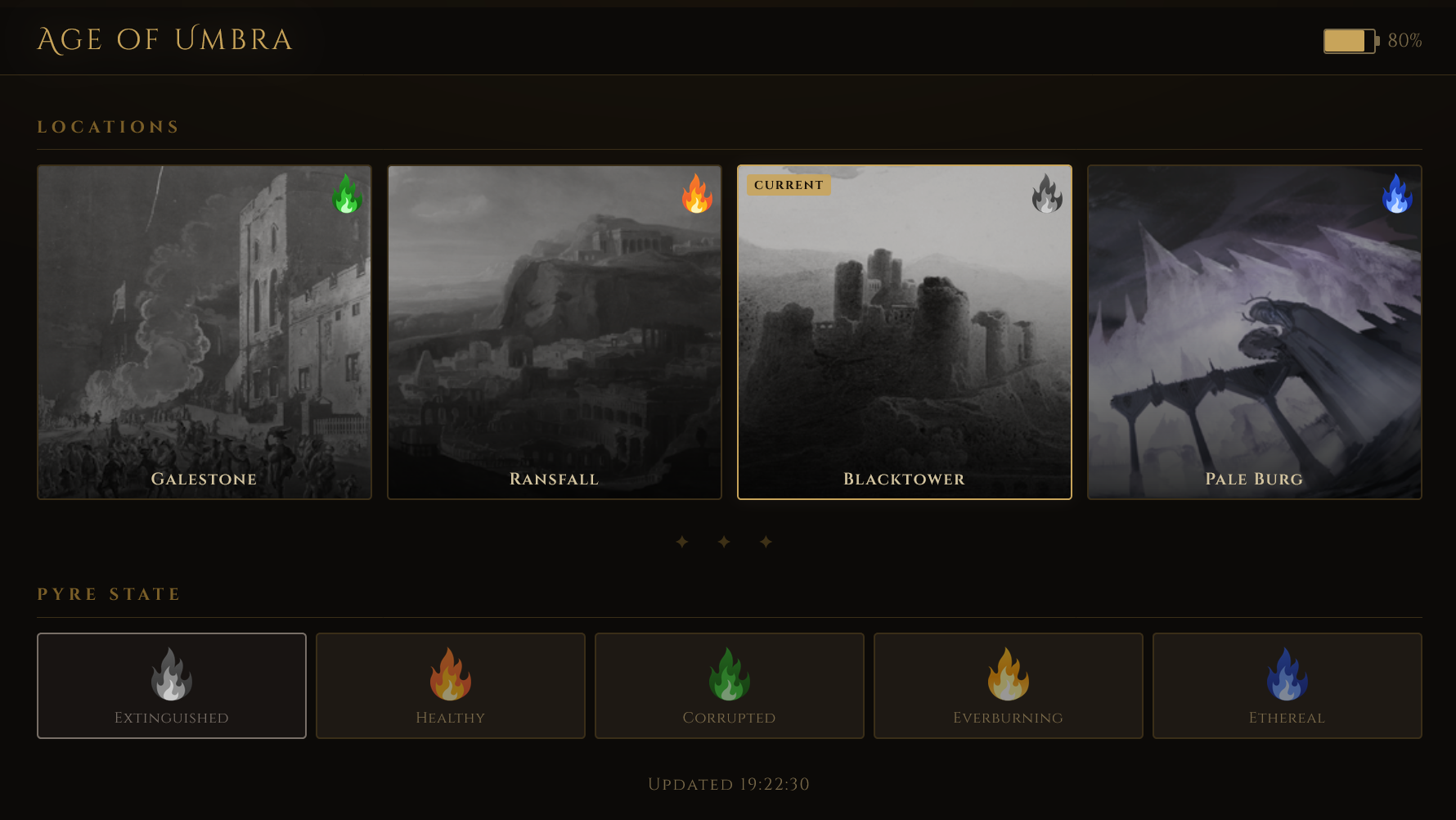
The front-end was built as an SPA dashboard, showing the 4 pyres as tiles, their current states, and the battery level of the device. A row of buttons changes the selected pyre’s state. HTTP POST requests mutate the GameState (as does tapping the flame icon on the touchscreen), causing a change event to be broadcast over the SSE stream. This keeps the front-end in sync with the model and the on-device display.
A local test script and MockBatteryState were sufficient to iterate quickly without uploading every change to the device (followed by a slow reboot and reconnect to WiFi).
Battery management
Being a portable device, it is very important to be able to monitor the battery state of charge. Although my LiPo cell is protected from catastrophic discharge by the BMS, there is otherwise no hardware mechanism to prevent it getting critically low.
I encountered some limitations with the ESP32 dev board (and, again, my lack of knowledge/experience in this area!). Firstly, software cannot detect the charging state on this board4 so we must fall back to heuristic detection. Secondly, the recommended formula to convert ADC reading to battery voltage never seemed to match actual multimeter measurements. Waveshare support confirmed to me that the sense path has a MOSFET drop that the reference formula doesn’t take into account, so I characterised it empirically.
I ran the device flat, periodically logging what the board ADC reported against a multimeter. With this I was able to determine:
- How the reported ADC value tracks reality.
- Where the cell’s real limits are.
- How long the cell sits in each part of the range (i.e. its discharge curve).
Aiming for a conservative “safe” range of (actual voltage) ~4.2V = 100% to ~3.3V = 0% (giving myself comfortable headroom above a 3.0V limit), the discharge curve breaks into 5 thresholds, each representing a roughly 20% charge increment. We map the reported ADC values into one of these ranges to get the percentage.
Luckily, with this configuration and load, there is no overlap between the battery and USB-powered (i.e. charging) ADC value ranges. Therefore anything above a certain threshold means “battery is charging” and that range has its own separate mapping to % level.
Housing and 3D printing
I custom-designed and printed a few pieces of housing: the main enclosure which would contain the electronics and have the hex tile map sit on top, and the hex-shaped body for the ESP32-S3 and display to sit within. I also printed the hex tile map (using STLs by Hexton Hills), and finally some translucent “flame caps” for the LEDs.
STLs and print settings can be found in the hardware directory of this project’s GitHub repo.
Main enclosure
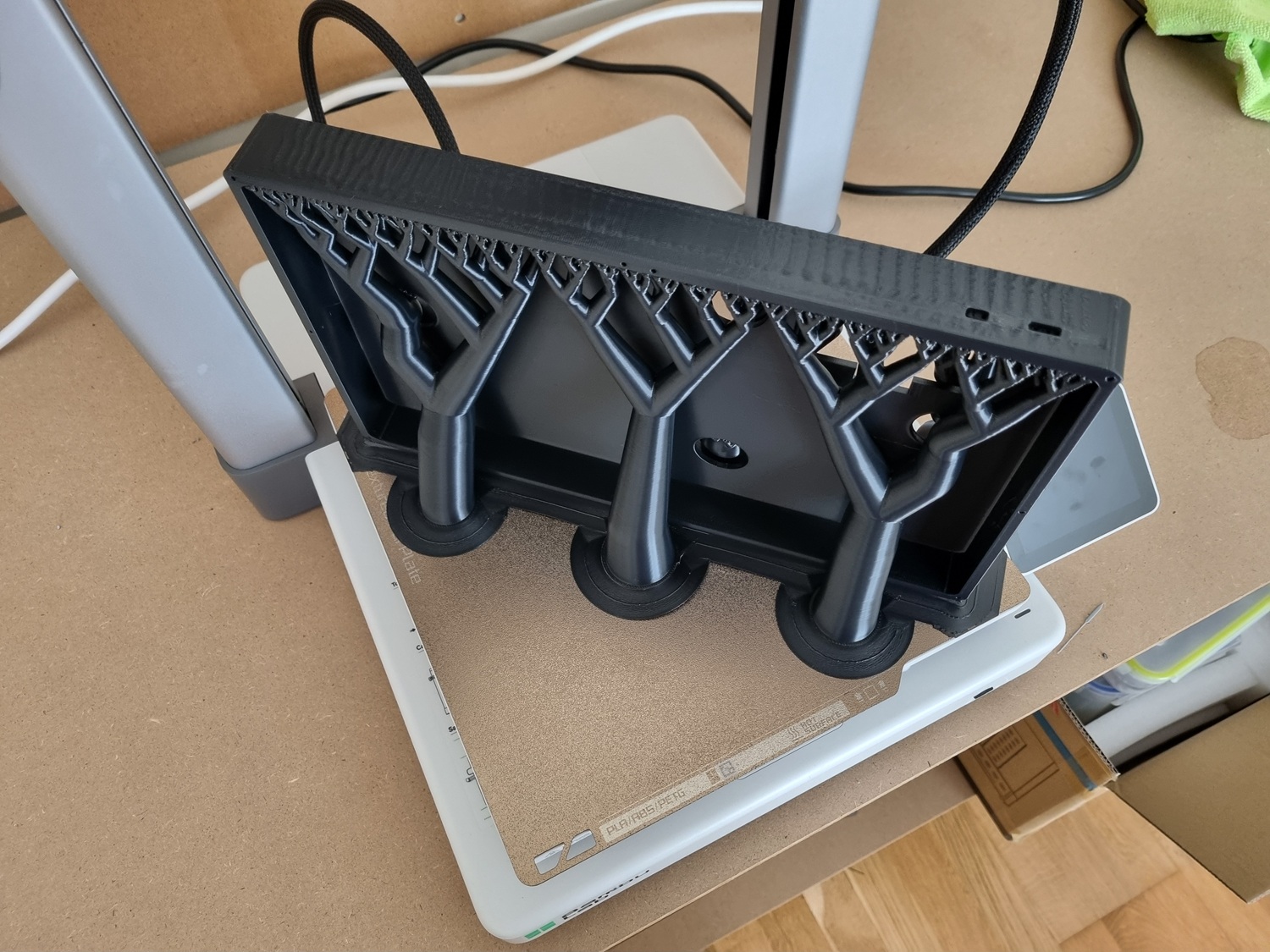
The main enclosure was designed from scratch in TinkerCAD. It comprises a single-piece 300x180x30mm body with an indentation for the hex tile map to sit, and holes in the sides for the USB-C port and power slide switch. These took quite a bit of prototyping to get right. The holes beneath the tiles for the LEDs and the ESP32-S3 dev board to sit in also required a few test prints.
I was able to – just about – print it in one piece on my Bambu Lab A1, on its side, arranged diagonally across the build plate. Despite lowering nozzle speeds and other settings to prevent vibrations from affecting the print as it grew taller, the result still has some “wavy” artifacting on the top edge. Ideally one would use a printer with a sufficiently large build plate to print this piece flat.
The back panel, being thinner, had to be printed flat in two halves. It is secured to the back of the main enclosure using 10x 16mm M2 screws.
I stupidly didn’t bother to measure the electronic components and how exactly they would fit in the back of the body before printing. I ended up having to make extra room by expanding and re-printing the back panel, instead of having it just be completely flat. The upshot is that the full box (main enclosure + back panel) is very chunky – around 42mm tall!
Hex screen body
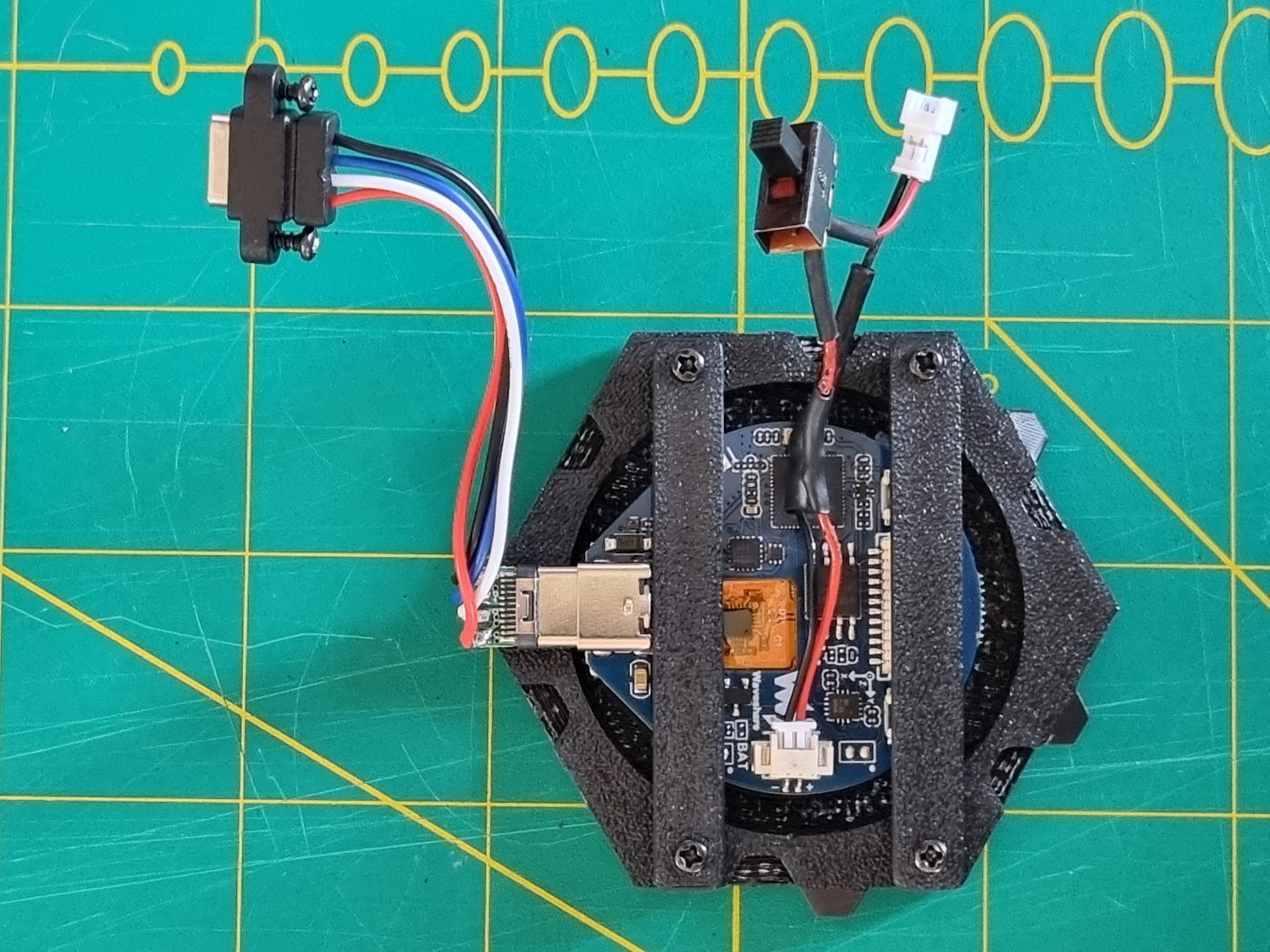
For the hex screen body, I started with a Hexton Hills-sized hexagon in CAD and cut out a space for the board to sit. This, again, took a fair amount of trial and error and prototype prints to converge on a snug fit. To secure the board in place, I created two horizontal “retaining bars” that would screw in place with a couple of 10mm M2 screws. They apply light pressure to prevent the board from slipping out of its slot.
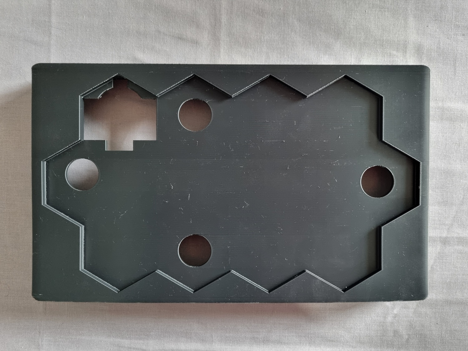
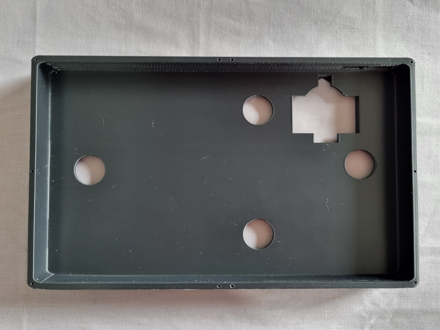
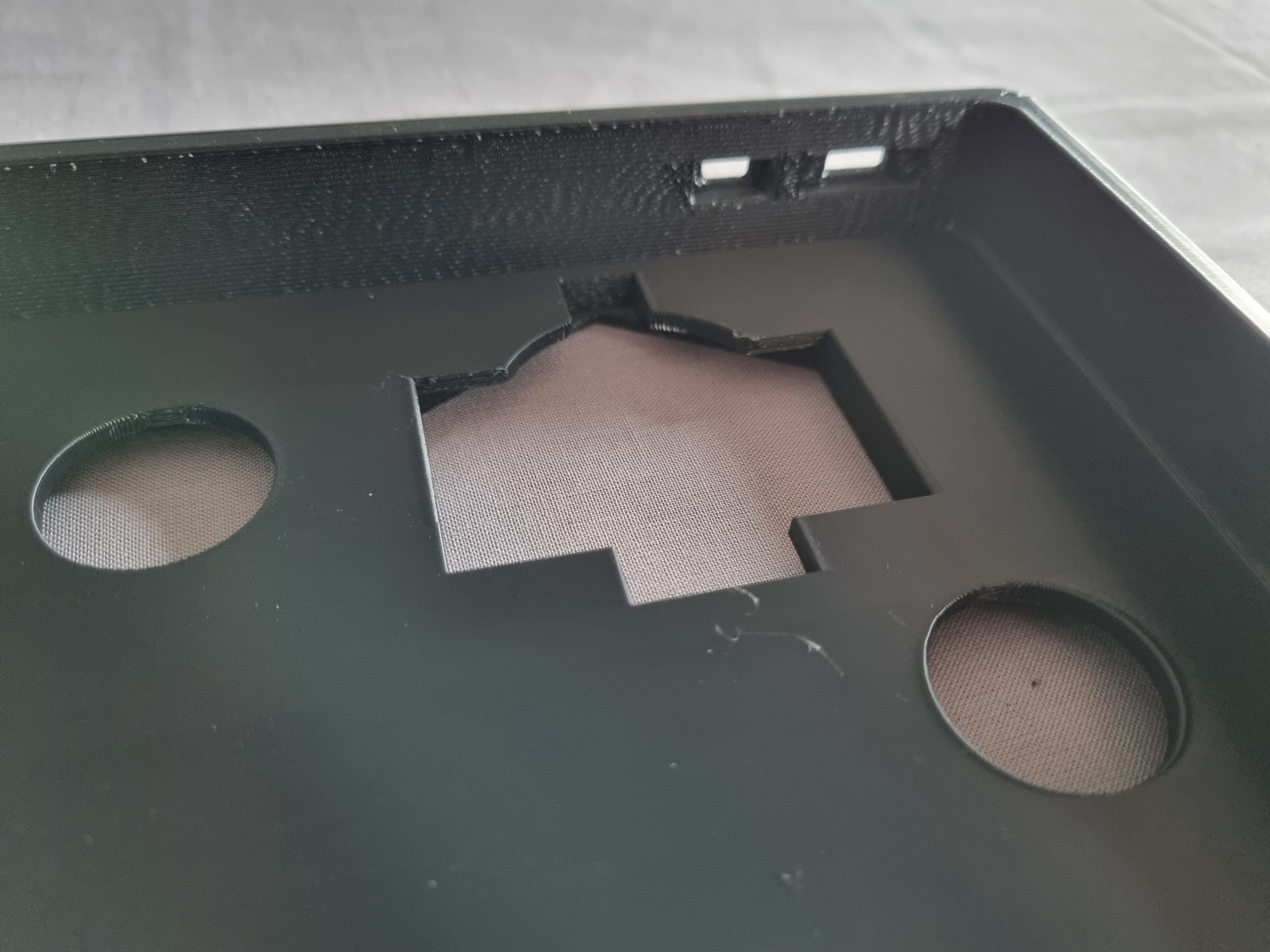
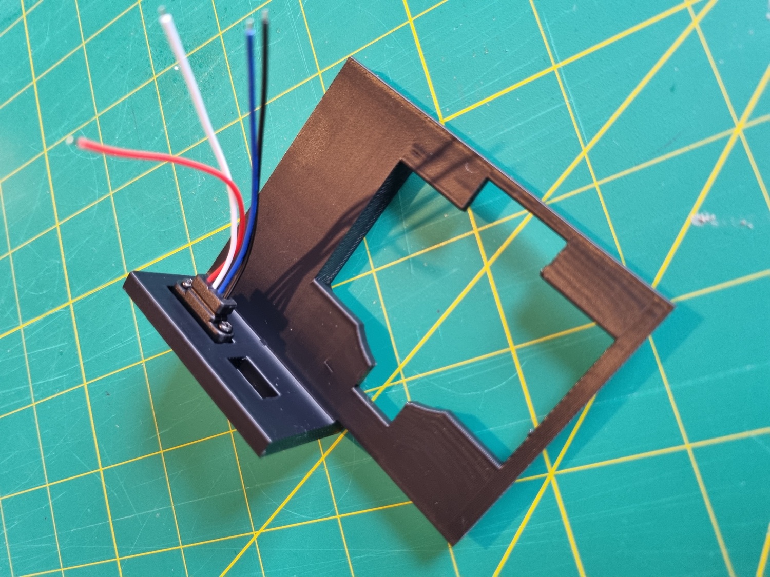
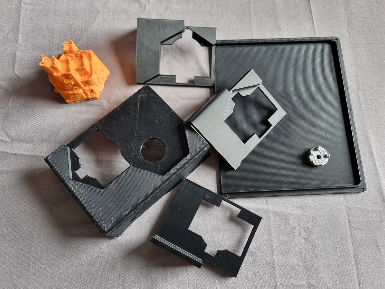
Hexton Hills map tiles
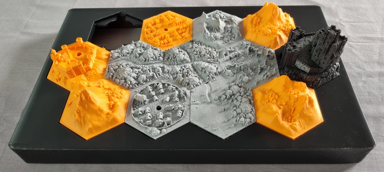
I printed the map design as above, comprising 12 tiles. To accommodate the LEDs in the town hexes, I added some slightly tapered holes in CAD, allowing the LEDs to be inserted from underneath. The “Pale Burg” fortress was more complicated – I hollowed out the interior and the (microscopic!) windows, intending to install the LED deep inside to shine out in a vaguely ghostly way. This also meant that I had to reprint this piece using black PLA: originally I had printed it in orange, but this would have resulted in that colour bleeding through the thin walls.
Once printed and cleaned, the tiles were all superglued together into their final configuration in preparation for painting.
Flame caps
To diffuse the light from the LEDs and make them look more convincingly “flame-like”, I printed some flame-shaped caps using Anycubic High Clear resin on my Elegoo Mars 3 Pro. I purposefully did not follow the advice to “clear up” the prints post-processing, leaving them frosty instead of fully transparent.
Painting
My goal was to capture the dark and eerie tone of the Age of Umbra setting by depicting the world illuminated by moonlight. Therefore I went with a muted and desaturated colour palette, and strong directional highlights. My rough recipe was:
| Basecoat | Strong zenithal prime (white over black) from north only, to simulate moonlight from that direction. | |
| Ground | Mummified Grime (Army Painter Speedpaint 2.0). | |
| Mountains and stone buildings | Nuln Oil wash (Citadel). | |
| Light drybrush highlight with a mix of Fenrisian Grey (Citadel) + White (Vallejo), in the direction of the light. | + | |
| Trees and foliage | Gunner Camo (Army Painter Speedpaint 2.0). | |
| Rough highlight with a mix of Fenrisian Grey + White + Gunner Camo, in the direction of the light. | ++ | |
| Town roofs | Goddess Glow (Army Painter Speedpaint 2.0), trying to leave areas in shadow as pure black. | |
| Initial rough highlight with a mix of Fenrisian Grey + White + Goddess Glow, in the direction of the light. | ++ | |
| Final bright highlight of White + tiny amount of Fenrisian Grey on edges that would catch moonlight. | + | |
| Final | Airbrush varnish with Vallejo Matt Varnish. |
I’m not quite sure it fully reads as “moonlight” but I’m happy enough with how it turned out, and the light from the LEDs, diffused through the translucent frosted “flame” caps, does illuminate each town centre quite pleasingly.
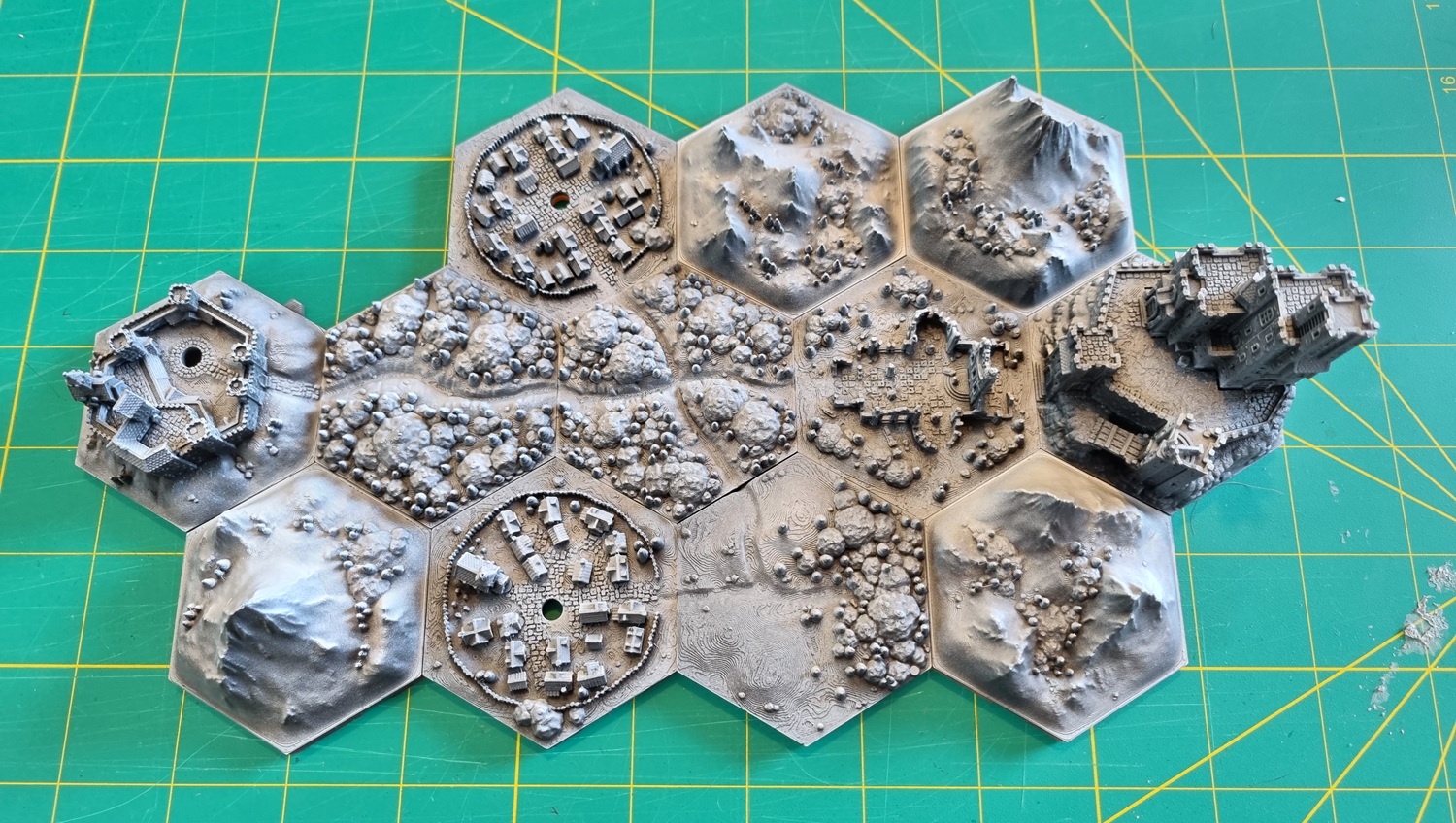
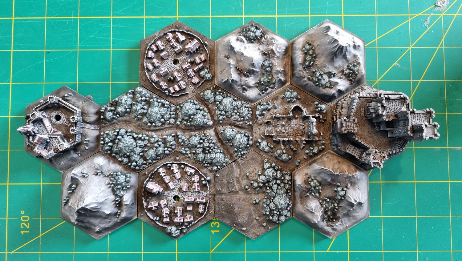
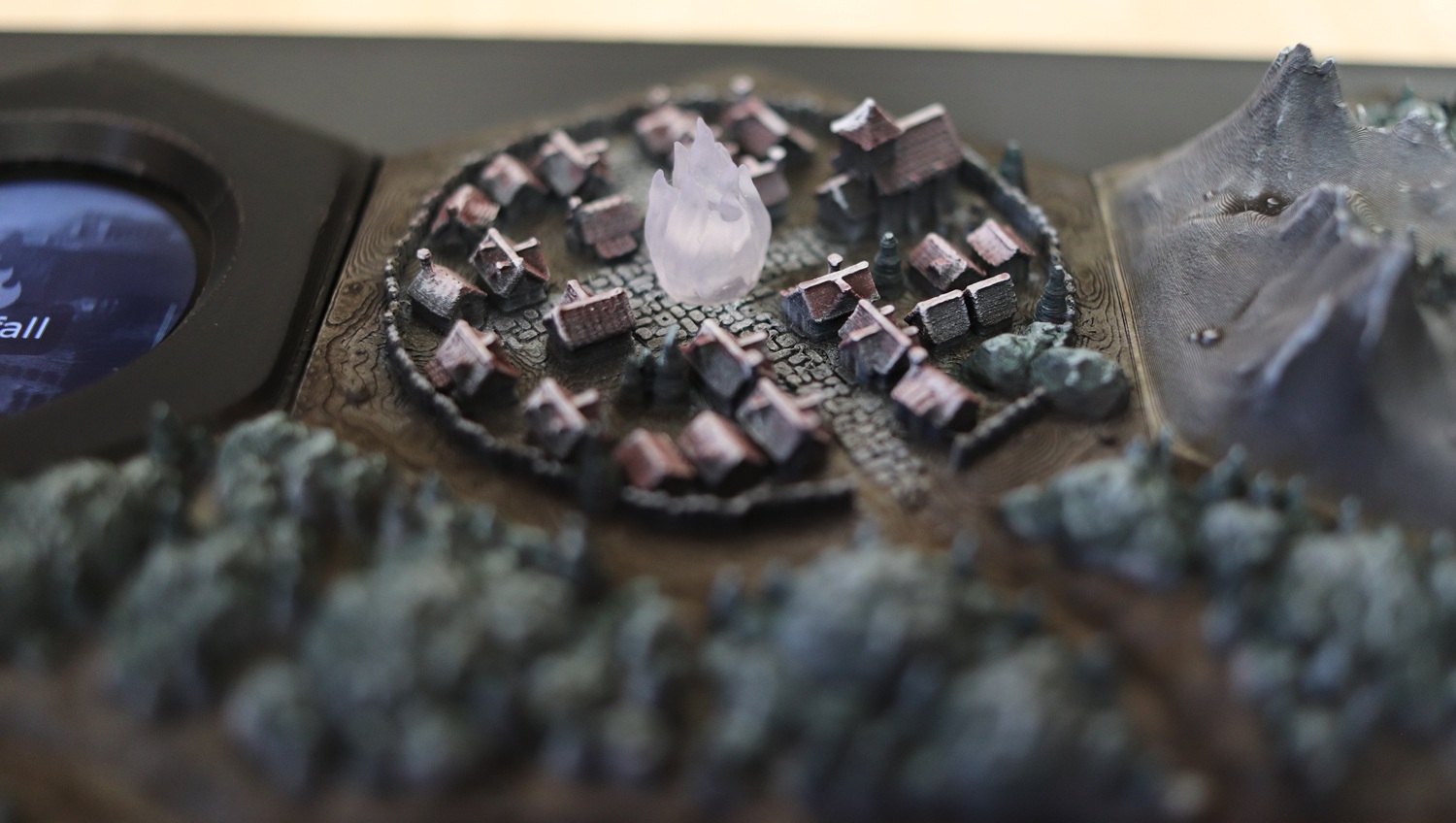
Final assembly
The painted tile map and hex screen body were glued in place on top of the main enclosure using copious amounts of superglue.
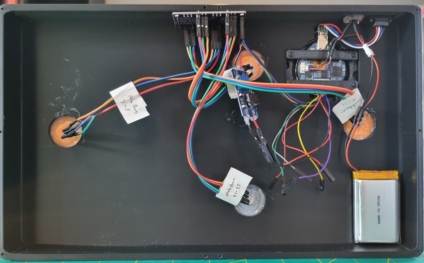
Electronic components, including the battery(!), were hot glued into the back of the enclosure. LEDs were routed to their appropriate tiles and hot glued – sticky labels around the wire bundles were very useful to keep track of which LED corresponded to which hole! Flame caps were superglued over the tops of the LEDs.
The USB-C port was inserted flush with the outside of the enclosure and screwed in place. A superglue and hot glue combo was used to secure the slide switch in its slot – I was worried the torque of being pushed and pulled would make it pop out, but it has stayed put so far!
Finally, with all internal components correctly installed, the back panel was screwed down.
Lessons learned
-
Dev boards save an enormous amount of time, but I should expect them to have design compromises and flaws. With this board in particular, the backlight brownout issue is a major problem that would make me reconsider this device for use in other projects. The state of charge being invisible to software is a minor issue which is annoying, but I was able to work around it.
-
Measure three times and print once! A few reprints could have been avoided had I been more meticulous.
-
Batteries are to be respected: I am still a little nervous that my LiPo cell is unsafe, despite taking precautions with the BMS and the physical slide switch. I also, in hindsight, would not have hot glued it to my housing…
-
MicroPython and the ESP32 are fun to work with. It felt magic when I got a PoC bit-banging MicroPython driver to light up LEDs on the TLC5947 that was hooked up to a breadboard. There’s a visceral rawness to it that modern software engineering doesn’t often elicit in me these days.
Conclusion
Overall I had an absolute blast building this thing. It was particularly great to get my hands dirty in the physical world – soldering electronics, designing, printing, and painting 3D objects – in a way that AI tools can’t just… do. I learned a ton that I can take straight to the next project.
Most importantly, it was a hit at my Daggerheart table, if slightly overkill! I can’t wait to roll it out again when I run this campaign with another group.
Other links
I’ve published code, schematics, resources, and in-depth technical details for this project on GitHub.
On 11 May 2026 I posted this project on r/daggerheart, where I got some very nice comments from the community :-).
-
4x3 = 12 PWM outputs required, but the board has only 6 GPIOs broken out. ↩︎
-
An AliExpress clone of an Adafruit module. ↩︎
-
Background images are from paintings by various 18-19th century artists, as well as from official Age of Umbra materials. Full attribution can be found in the GitHub repo. ↩︎
-
The schematic shows the ETA6096 STAT pin, which carries this state, completely unconnected. ↩︎